Mount your ETX90 OTA
On Your ETX60/70 Mount
Copyright Gene Chimahusky 2002 All Rights Reserved
Blueprint added 10/28/2002, see end of page
Does it work? I would say yes! Etx70 mount with an autostar 494 coupled with a 'new' 90 OTA from an etx90M.
A key is getting the DEC axis perpendicular to the RA axis. Once that is done it put every object in the inner
2/3 of the 26mm MA eyepiece, in every quadrant of the sky from 20alt to 82+alt for an hour going round and round in alt/az mode. The only issue I saw was the etx70 mount, when tracking in alt/az mode has a high freq vibration that shows itself at higher powers, made it difficult to split the epsilon lyra doubles at 210 power, or maybe it was the lower altitude combined with heat currents off the shopping plaza less than a third mile away, like little fuzz balls with no diffraction rings. So far so good.
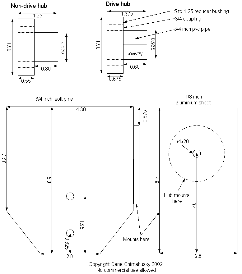
This mount adapter is made from commonly available PVC pipe fittings. These fittings have
nominal sizes that are slightly larger than what is required.
Fabrication guidelines:
NOTE: Measure three times, cut once and feel free to change the measurements in the blueprint. These are what
I measured for my scope and may vary with yours!!!!
It is a necessity to have at least a dial vernier caliper for this work, and know how
to use it, including the depth gauge end of it! You will want to make accurate
measurements to 0.005 inches or better, especially on the stub shafts where they
insert into the scopes DEC axis adapters!
The sizes given for the 1/8 inch aluminium plate are what I had available. What is semi
critical is the location of the line of the DEC axis drawn thru the OTA for good balance.
You want this line to be at the balance point of the OTA, or matching as close to exactly
where the fork adapters DEC axis from the original 90RA/90M would be!
The DEC axis stubs are fashioned from 3/4 inch PVC pipe. The nominal OD of the pipe is
1.05 inches. I used a 45 degree Sched 40 conduit elbow which is basically has two straight
ends that can be cut off after sanding to correct OD instead of having to buy a 10 foot
length. The required OD is 0.965. To facilitate this I used 80grit sandpaper and sanded and
sanded (and sanded) in to about 1 inch from the end till it fit into the original fork
arm adapters.
The next piece of PVC is a coupling for 3/4 inch PVC pipe. The un-sanded side of the
stub shafts fit into the coupling. The nominal OD of the coupling is just slightly larger
than the nominal OD of 1 1/4inch PVC pipe, again time to break out the sand paper and
sand till it fits into the 1.5 to 1.24 reducer bushing.
To assemble each axis adapter cut the 45degree elbow ends off to fit fully into the coupler with
the sanded end out, do not cut off the sanded ends to size yet. Make sure it is fully
into the coupler by using a wooden block as a cushion as you hit the block with a hammer
lightly to seat the parts. Remove the stub shaft from the coupler.
Cut the sanded coupler so it fits fully into the reducer bushing and the end of the
coupler sticks out slightly from the surface of the bushing. Then get the sandpaper
(or files) out again and sand the two parts as a unit so the hex head size of the bushing
and inserted coupler are flat (there are usually raised letters on the head, make them
all go away!).
You then have a full reducer bushing with a cut off coupler inserted. Now insert the stub
shaft into the coupler. Does it 'look right' ? Good!
Take the assembly apart and then glue them all together to form a rigid part. Use the
solvent type glue for PVC. Work fast when re-assembling, that glue grabs FAST! Use
a wooden block to use as a cushion as you pound the parts together with a hammer.
The rigid assembly is then cut to match the reducer bushing height shown in the 'blueprint'.
Cut slightly over long and sand to the correct dimensions.
Cut the stub shafts off now to match the length given in the blueprint.
NOTE: Measure your assembly as a unit assembled on your telescope!
Would hate to cut anything too short and have to start over!!!
DEC axis perpendicular to RA axis procedure:
The base of the 90 OTA has two mounting points for 1/4x20 tripod attachment. If you only mount to the second one, the one farthest from the rear, it gives you a good pivot point for slight adjustment of the OTA pointing.
Set the base on a level surface or on the tripod you use. Critically level the base. Then point the OTA straight up and measure the level across the lens cap from fork arm to fork arm. Rotate the OTA around the attachment screw pivot point., when you get a good level, tighten the attachement screw down. This is not super percise but works well enough. You can make further adjustments in the field by slewing between two stars that have roughly the same AZ but are seperated widely in DEC. A slew between the lower ALT to the higher ALT 'should' show no left or right movement of the target in the FOV. When you get this movement to as small as possible you are also effecting the ALT pointing accuracy. The reason for this is the shortest distance between two points is a straight line, the path the autostar will take. If you are not perpendicular the object will be off one way or the other in AZ and also fall short in ALT.
Milling the 'pins and slots' on the non driven hub.
The locations of the required holes and slots on the non-driven arm can be easily done by putting 'gobs' of graphite on the pins and arcs, then insert the axis stub shaft into the part and press down and turn ever so slightly back and forth. Remove the adapter and you should have graphite markings on the PVC hub where you must drill and mill. I found milling PVC can be done easily with a small drill press. Set the depth gauge on the drill press to the height of the pins/arcs, drill the pin holes. Next drill holes at the start/mid/end points of the required slots. You can then feed the part sideways very slowly along an arc between the holes drilled at the slot points.
Making the keyway in the driven arm:
The driven arm has a key on the arm adapter and the clutch plate. To make the keyway on the stub shaft I first started out sawing with a hacksaw blade held in my hand, making sure the cut was centered on the long axis. This then gave a guide for mulling the keyway as was done with the slots on the undriven arm. THis is a small keyway so use an appropriate sized drill bit.

Larger View

Larger View

Larger View

Larger View

Larger View

Larger View

Larger View

Larger View

Larger View
This information is for free use by individuals or groups
Commercial use is prohibited without permission
In fact any money changing hands because of this info requires permission!
Gene Chimahusky