Introducing the GCUSB-nStep2 stepper motor controller
Availabile Now!
Email me if interested in more information: astrogene1000_stuff AT yahoo.com
Provides for:
USB interface or Standalone operation with/without wireless
Modular plugin expansion
Wireless interface for bluetooth communications
Display with buttons for configuration, speed and direction control, 16 char/2line
Adaptable for other uses (home sensor, rs232)
See ‘Technical Information’ below
Temperature sensor and temperature based focus (Standalone or provided by ASCOM driver)
Recall, Save and GoTo 5 positions as you change from eyepiece to camera, etc, just focus once and GoTo when you change
ASCOM driver supported over USB or wireless
Base module remembers all settings across power on’s
Firmware is field flash upgradeable on the main module
Temperature spec’s of –40C for main and wireless module, –20C for physical display or the display module
See GCUSB-nSTEP page for description of ASCOM driver
See Youtube demo videos part 1and Part 2
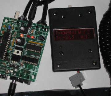
The unit with optional wireless, temperature probe and display module attached.
Temperature probe can have up to 5M long wiring,
Attach it right to the tube of your scope for accurate readings to +/- 0.5C
Coiled cords are 12ft long when fully expanded, take little space when contracted.
At this time the display unit circuit boards are on order and expected week of Jan 24.

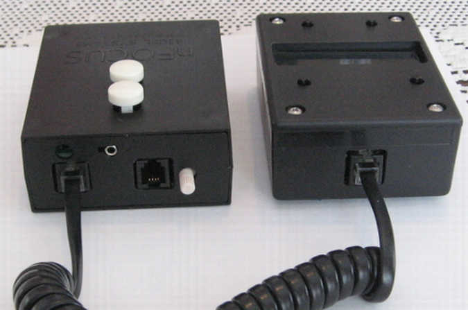
Display module left, main module right

Main module left, display module right
Update March 3, 2011
These units are in continuous stock, available to ship in 2 days or 5 days
depending on whether I have units assembled, I usually always have units assembled and tested.
There is an up to 5 business day ship time for non-assembled units
These are custom built and tested for 4-8 hours each
If this is not acceptable to you, please do not buy
If more than available stock is ordered I will refund money immediately when oversold condition is recognized
( 24 hours max) and provide an expected availability date.
I will only ship to North and South America, Europe, Japan, Australia and New Zealand.
If you are from Italy -contact me- first for shipping quote
Orders from a country I will not ship to will be promptly refunded and not fulfilled
|
All units RoHS |
30 day return (except for buyers remorse) |
|
Main Module - $199.95 USD + shipping Main module, USB cable, stepper cable, 12V DC adapter |
|
|
Display module - $129.95.00 USD + shipping Includes 12ft coiled cable to main module |
|
|
Wireless Module - $94.95 USD + shipping Includes 12ft coiled cable to main module |
|
|
Temperature Sensor - $19.95 USD + shipping Includes sensor and 6ft cable to main module |
|
|
12V AC adapter - $19.95 USD + shipping USA 2 prong plug, 100V-240V capable |
|
|
View Cart |
|
ASCOM driver screens


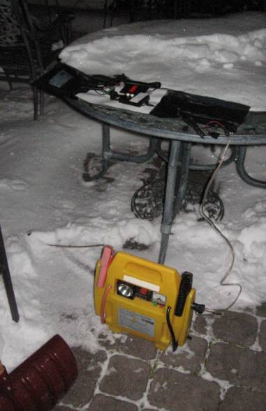
Temperature testing to -20C outside
It does not get super cold in the Philly area so I took advantage of one night with –20C temperatures
Unit
is connected wireless, who wants to sit outside in the cold?
This image taken about 15 minutes after the next one, got too cold to stay outside!
Unit connected wireless to warm and cozy inside the house

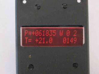
The units up close in the cold showing -18.5C
The ouside environment
The base module

The Bluetooth
module
Not much to see, led indicates paired and connected status.
Range 20 meters or 100 meters available

The Display unit
Buttons usage:
Upper left: Next menu
Upper right: Previous menu
Lower left: focus or change current menu item
Lower right: focus or change current menu item
Temperature
compensated contrast, set it once and forget it!
The menu structure:
|
|
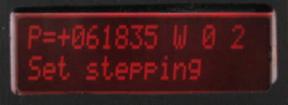
Top level menu showing: Current position Probe temperature Step type (W/H/F) Coils On/Off Current = 0 = off Phase select: Current = 2 The current steps/second (149) The stepper will move if the In/Out buttons pressed only in on top level menu. The current position will update continuously if the main module or display module in/out buttons are pressed The current steps/second will show the main modules rate if main module in/out buttons pressed. |
|
|
The twist dial at top: Set current step rate (now 88) Will only range from 6 to Max Speed (see below) |
|
|
Select step type: Top = W = Wave Stepping Bottom = H = Half Stepping Choices: Wave, Half or Full torque |
|
|
Select Coils On/Off after movementTop = 0 = Off Bottom = 1 = Leave on |
|
|
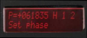
Set phase drive order: Top = 2 Bottom = 1 Choices = 0, 1 or 2 This accounts for the wiring order of the stepper. |
|
|
Set display brightnessRange = 0 (off) through 31 |
|
|
Set display contrastRange = 14 through 31 |
|
|
Backlight on timeRange 10 through 310 seconds After last button is pressed keep backlight on for this length of time |
|
|
Set max step rateRange 99 through 1496 steps/second |
|
|
Force zero current positionPress up/down to zero, will confirm on next menu if up/down pressed. To cancel, press menu select buttons |
|
|
Confirm force zero position Press p/down to zero. To cancel, press menu select button |


The
bottom of the board

Technical Information:
1)
Stepping rates
The unit provides for a wide range of stepping rates, some of which can drive drastically faster than most steppers can handle.
The maximum rate is 1496 steps/second, the minimum rate is 5 steps/second. The maximum rate is controlled in the ASCOM driver and in the hand unit itself.
The display module provides for a more limited range of step rate selection, offering the choice of 25 speeds from 1496 to 6 steps/second.
2)
Stepper driver
The unit uses high voltage/medium current mosfet output drivers capable of driving 1 AMP/phase.
3) Optically coupled when PC attached
When connected to the PC/Mac, the output stages are isolated from the processing side via optical coupling.
The 12V supply is only used for the motor and the USB 5V is only used for the PIC, wireless and display module.
This prevents any voltage gound loop issues when connected to PC and stepper power supply.
3)
Standalone
operation and Wireless
The base unit can be jumpered for running standalone without USB or wireless interface.
The base and optional modules then take power from the 12V supply.
Standalone operation uses same firmware load as wireless operation.
4)
Wireless
The expansion wireless module is based on the Roving Networks RN-41 (for 100m) or the RN-42 (for 10m-20m) for wireless interface.
At this time the USB and Wireless interfaces are mutually exclusive, both cannot communicate at the same time. It is two separate and distinct firmware modules that is loaded into the base unit.
Flashing firmware is an easy process on these units. A utility is provided that puts the unit into 'flash mode' and then launches the flash utility itself. You select the firmware load to be flash and press a button, about 10 seconds later it is complete.
5)
Expansion ports
The two expansion ports shown provide for 5V, GND, TX and RX TTL serial interfaces. This means that adapting the unit to rs232 DB9 serial interface in place of wireless is a simple add on module that converts rs232 voltages to TTL voltages. No firmware changes are required.
Pinouts (looking into the connector, upper left = pin 1)
Pin 1: 5V
Pin 2: Module RX (To module)
Pin 4: Module TX (From module)
Pin 4: GND
The Display port runs at 19.2k baud and the Wireless port runs at 9600 baud. Both are 8/N/1.
6)
Expansion port
digital I/O
It is also possible to provide 2 digital I/O signals per expansion port in lui of serial communications. This means that adding a ‘home’ sensor is a simple add-on on module providing a logical ‘0’ or ‘1’ to indicate home position. Firmware supporting this is planned for the future.